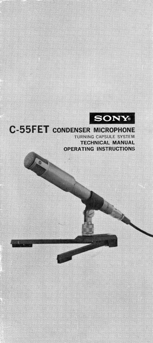
The Sony Models C-55FET and C-55P
cardioid condenser microphones – 1970
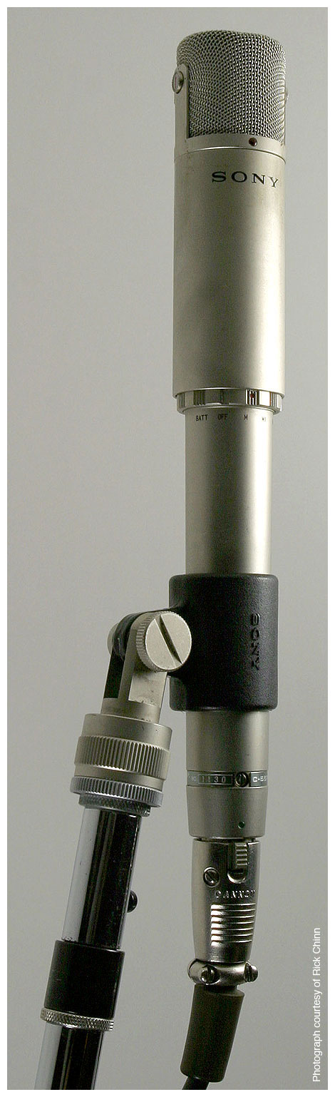
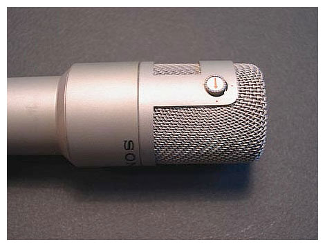
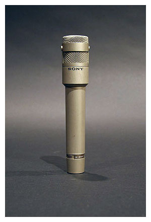
The original C-55 above is battery-powered, and uses a DC-DC converter to provide polarization voltage to the condenser microphone capsule. The C-55P FET microphone omits the DC-DC converter, and polarizes the microphone capsule from the P48 powering. (An image of the Model C-55P FET can be seen below.)
General Description
The Sony Model C-55P is a lightweight handy type uni-directional condenser microphone intended for broadcast or recording studio use, with features as follows.
- Phantom Powering System
The microphone is operated from an AC power source by using Sony AC Adapter AC-148A (optional). The shielded two-conductor microphone cable is used as both an audio signal cable and a DC power supply cable by connecting to the AC-148A. Positive DC current is supplied to the microphone through the inner two conductors of the cable, and negative DC current through the shield conductor.
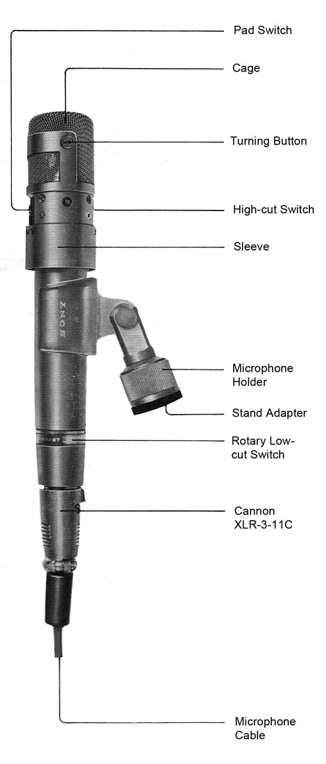
- Low-Cut Switch
This switch has the following three positions: M for a flat frequency response, M1 for slight attenuation of low frequencies, and V1 for extreme attenuation of low frequencies.
- High-Cut Switch
This switch has the following two positions: Flat frequency response, and Attenuation in the frequency range higher than 5 kHz.
- Pad Switch
This switch has the following two positions: 0 for no attenuation, and -8 dB for eight decibels of attenuation over the entire frequency range, used for high-pressure sound pick-up.
- Capsule Angle Change
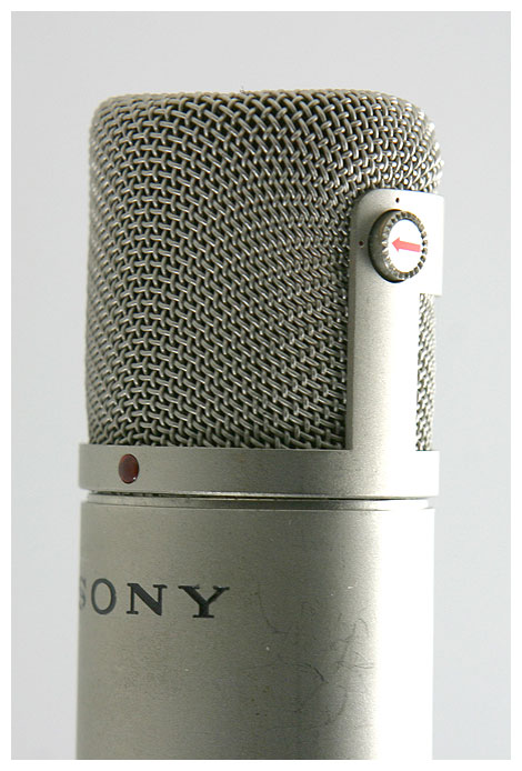
The capsule angle can be changed through 90 degrees vertically by pressing the two side buttons.
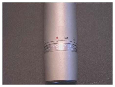
The Model C-55P FET microphone shown here has its rolloff selector ring in a different location from that of the Model C-55 seen at the top of this page, and does not have the “BATT” nor “OFF” switch positions. Images and a description of a P48 power supply designed and built by Rick Chinn can be viewed here. Use your “Back” button to return to this page after you view Rick’s work.
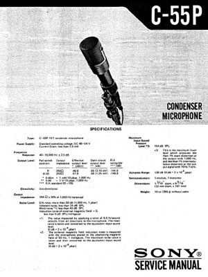
SPECIFICATIONS
Type: C-55P FET condenser microphone
Power Supply: Standard operating voltage; DC 48–54 V
Current Drain: Less than 2.5 mA
Frequency Response: 40–16,000 Hz ±2.5 dB
Output Level:
Pad switch Output Effective Open circuit EIA
position impedance output level output level rating GM
*(dBm) **(dB) ***(dB)
————————— ————————— ———————————— ————————————— —————————
0 250 Ω –49.8 –50 (3.16 mV) –141.8
–8 dB 250 Ω –57.8 –58 (1.25 mV) –149.8
*0 dBm = 1 mW/10 µbar, 1,000 Hz
**0 dB = 1 V/10 µbar, 1,000 Hz
***EIA standard SE–105
Directivity: Uni-directional
Output Impedance: 250 Ω ±20% at 1,000 Hz balanced
Noise Level: S/N ratio: more than 50 dB (1,000 Hz, 1 µbar)
Inherent noise: less than 24 dB-SPL
Wind noise† less than 43 dB-SPL
Induction noise of external magnetic field‡
less than 5 dB-SPL/milligauss
†The value measured by applying a wind of 6.6 feet/second
velocity from all directions to the microphone. The mean
value is taken and converted to the equivalent input sound
level:
(0 dB = 2 × 10⁻⁴ µbar)
‡The external magnetic field induction noise is measured with
the microphone placed in the alternating magnetic field of
50 Hz, 1 milligauss. The maximum noise value is taken and
then converted to the equivalent input sound level:
(0 dB = 2 × 10⁻⁴ µbar)
Maximum Input Sound Pressure Level: 154 dB-SPL. This is the maximum input level which produces less than 1% wave distortion at the output with 1,000 Hz, and less than 1% intermodulation distortion at the output signal with 70 Hz to 7 kHz
Dynamic Range: 130 dB (0 dB = 2 × 10⁻⁴ µbar)
Semiconductors: 1 module, 1 transistor
Dimensions: 1.3 inch diameter × 6.56 inches length
(33 mm diameter × 167 mm length)
Weight: 10 ounces (280 g) without cable
Numerous technical illustrations, including some not shown here, can be found in the three booklets that are available for downloading from the bottom of this page.
Download the C-55P Operating Instructions.
Special thanks to Jim Zuehsow for this manual.
Download the C-55P Service Manual.
Special thanks to Ms. Kimberly Stewart
of Sony Corporation for this manual.
|