Matching Impedances
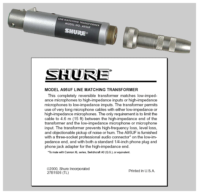
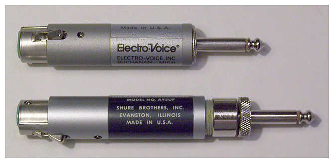
The Electro-Voice Model 502CP and the Shure Model A95UF microphone matching transformers are physically and electrically similar. As can be observed, the Shure unit has a removable quarter-inch phone plug, while the Electro-Voice phone plug is integral. Furthermore, the Electro-Voice unit’s input impedance is fixed at 150 ohms, while the Shure unit’s input impedance can be set to accommodate 75 to 300 ohms, or 19 to 75 ohms, by disassembling the transformer and exchanging two leads. The procedure is covered in the Shure A95UF Data Sheet, which is downloadable from this page.
A transformer consists of two coils that are magnetically joined because they are close to one another and because they are wound around the same magnetic core. The input signal goes to the primary coil and the output signal is taken from the secondary coil. The transfer of voltage will be in proportion to the number of turns in the coil. If the secondary coil has fewer turns of wire than the primary coil, the ac voltage across the secondary coil will be lower than the voltage across the primary. A transformer can be used to step up ac voltage or to step down voltage. With appropriate impedance matching, all of the power going into the transformer is passed to the load. The output impedance of the transformer is stepped down or up along with the voltage. The transformer provides voltage amplification, not power amplification.
The term “impedance” refers to the total opposition to current flow in an ac circuit, and is measured in ohms. Using a transformer to match the impedances of a source and a load provides maximum power transfer between them. Examples of situations where this is significant include an audio amplifier and its speakers, a radio transmitter and its antenna, or a microphone and its console input. Microphones are generally classified as either “low impedance” (50 to 600 ohms) or “high impedance” (10,000 to 40,000 ohms). Professional microphones are in the low-impedance category.
Because of their relatively low voltage output level, microphones should be used in circuits that are compatible with their impedance. If this is not possible, an impedance-matching transformer should be used. Two examples are shown above. This helps to ensure that maximum power transfer will occur from the microphone into the preamplifier or amplifier to which it is connected. As can be read in the Shure commentary (above), low-impedance circuits are able to accommodate long microphone cable lengths without increasing noise or reduction in signal strength.
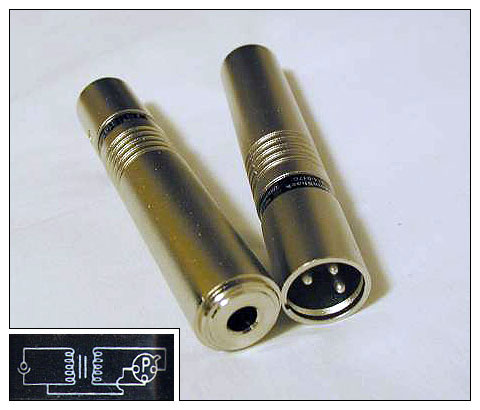
Radio Shack offers its own version, 274-017C, which provides a high-impedance unbalanced input via a quarter-inch phone jack, and a low-impedance balanced output via a male XLR (A3M). This is the opposite configuration from the other two companies’ transformers, which adapt a low Z input to a high Z output.
|
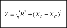
Calculating impedances
Where Z = impedance in ohms,
R = resistance in ohms,
XL = inductive reactance in ohms,
XC = capacitive reactance in ohms.
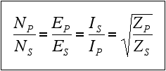
Transformer turns ratio
Where N = number of turns,
E = voltage,
I = current in amperes,
Z = impedance in ohms,
P = primary coil,
S = secondary coil.
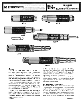
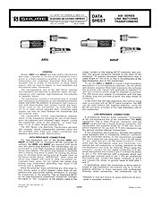
Download the Shure A95 Series Data Sheet.
Includes the A95A, A95F, A95P, A95FP,
A95D, and A95FD.