Altec (Western Electric) Models 639A and 639B multi-directional microphones
Listen to a Model 639B in its R, D, and C positions.
Differences in amplitude are authentic.
An Altec 639A with its three-position pattern selector switch.
An Altec 639B with its six-position pattern selector switch.
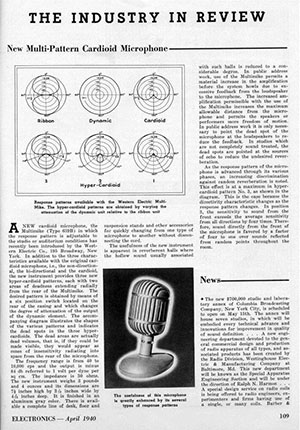
639A and 639B Cardioid Directional Microphones The 639-type Microphone is a general purpose magnetic microphone with directional characteristics which are selectable by means of a switch. The three basic patterns available are non-directional, figure eight, and cardioid.
Sensitivity The 639A and B open circuit output level is 84 dB below 1 volt/dyne/cm², 64 dB below 1 volt/10 dynes/cm².
Power Output Level –56 dBm for a sound pressure level (SPL) of 10 dynes per square centimeter, or –76 dBm for 1 dyne per square centimeter when the microphone is terminated with a resistance equal to its internal impedance. Experience indicates that the sound pressure produced at conversational level three feet from a microphone approaches 10 dynes/cm².
Frequency Range Substantially uniform from 40 to 10,000 Hertz. See Figure 2.
Signal-to-Noise Ratio The signal for 10 dynes per square centimeter sound pressure is 78 dB above the thermal agitation noise generated within the microphone, and 58 dB above for 1 dyne per square centimeter.
Directivity 639A Three patterns, C, D, and R, selectable through a three-position screwdriver-operated switch. Refer to Figure 1. At the angle of minimum response, the average discrimination with respect to 0° response is 20 dB over the range from 40 to 10,000 cycles per second.
639B Six patterns: R, D, C, 1, 2, and 3, selectable through a six-position screwdriver-operated switch. Refer to Figure 1. At the angle of minimum response, the average discrimination with respect to 0° response is 20 dB over the range from 40 to 10,000 cycles per second.
Impedance Average value is 40 ohms. Intended for use with equipment having a rated source impedance of 25 to 50 ohms.
Dimensions 7½" high, 4⁷⁄₁₆" long, 3⁷⁄₁₆" wide.
Weight 3¼ pounds.
Description and Operation The 639-type Microphone combines a dynamic moving coil pressure element and a ribbon velocity actuated element enclosed in a housing which serves as a protective guard and as a wind screen. The outputs of these two elements are used independently, or are combined in various proportions by means of a selector switch attached to the microphone, to yield several directional patterns. The 639A and the 639B are similar with the exception that the former has three selectable directional patterns, and the latter has six selectable patterns.
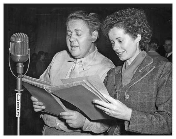
Charles and Elsa Laughton (nee Lanchester, married in 1929)
The moving coil pressure element when used alone has non-directional characteristics. The ribbon element when used alone has a figure eight pattern. The combination of the two elements results in a phasing of the output voltage causing the microphone to have a cardioid directional pattern. The three additional positions on the 639B microphone are variations of the cardioid pattern, with increasing pickup from the rear as the switch is turned from position 1 to position 3. These patterns are shown in Figure 1.
The 639-type Microphone is an excellent general purpose microphone for studio use in broadcasting and recording, and for remote broadcast pickups where it can be given reasonable care in handling. In addition, the several directional patterns will enhance operation of the microphone where audience or background noise must be controlled, and in public address pickups where acoustical feedback would ordinarily take place before a satisfactory reinforcement level could be reached. (Figure 1 shows the angle, in respect to 0°, of minimum pickup, and is useful for orienting the microphone to discriminate against unwanted acoustical feedback and reverberation.) It is particularly suitable for multi-microphone pickups of a large orchestra group where a sense of realism and an apparent increase of volume level is desired. This is accomplished by utilizing one 639-type microphone as a non-directional (position D) microphone for general orchestra pickup and several 639-type microphones (positions R, C, 1, 2 or 3) as accent microphones for soloists and individual groups of the orchestra which the operator may want accentuated.
From ELECTRONICS, November 1938.
The general mic will provide the necessary reverberation which is desirable for realism, and the accent mics will permit the individual groups to be accented for special musical effects. Skillful operation of the mixing of the various microphones will permit the operator to control, over a considerable range, the liveness of the pickup.
Designed by the Bell Telephone Laboratories and originally manufactured by the Western Electric Company, the Altec 639A and 639B Multi-Pattern Cardioid microphones have, for years, enjoyed an unprecedented acceptance by all phases of the audio industry. Indeed, it may be stated that the majority of all wide-range sound recording—from its initial appearance on motion picture soundtracks to the present achievement of magnetic tape—has employed one or more Altec 639 mics in virtually all phases of production. The immediate selection of pickup patterns provides the professional engineer with as many as six varying directional characteristics; the built-in two-stage windscreen, rugged protective housing, and numerous attachment and mounting accessories make the Altec 639 ideal for any application.
The factory-provided Type 442 connector.
Someone has modified this mic to accept the Type XLR connector.
Unlike competitive units which employ only a single ribbon and which vary the directional pattern by mechano-acoustic means, the Altec 639 is actually two independent transducer elements within a single housing. The electrical signals from these elements (one, a dynamic moving-coil; the other, a velocity-sensitive ribbon) are used singly or in combination to produce the different pickup patterns at the top of the page. Because no mechanical means are used, the Altec 639 provides increased durability, performance quality, and trouble-free operation—yet the 639’s versatility of application meets or exceeds that of other multi-pattern units currently available.
Figure 1
Both the 639A and 639B provide the broadcast, recording, and public address engineer with performance of professional standards; the difference between the two models is found only in the amount of readily-selected pickup patterns. The 639A provides the three most widely used characteristics of cardioid, bi-directional, and omni-directional pickup; the 639B furnishes three additional directional characteristics, each having full frontal sensitivity, but with varying degrees of rear sensitivity. These additional front-to-back ratios make the Altec 639B an outstanding choice for applications wherein two distinct sound sources, having equal intensities, must be handled with utmost clarity and separation (e.g., on stage versus audience pickup; dominant speech versus a more quiet manner of speaking, on each side of the microphone).
Each directional pattern of the 639A and 639B microphones may be easily selected with a screwdriver or similar tool, in accordance with the indicator marks on the rear of the microphone housing.
Figure 2
Low output impedance (30/50 ohms) permits the use of 639 mics at a great distance from the associated amplifying equipment without danger of increased noise, hum pickup, or deterioration in the quality of the transmitted signal. Each 639 mic is supplied with a zippered bag which covers and protects it when not in use.
Text and illustrations above are from Western Electric 639A and 639B Cardioid Directional microphones Instruction Bulletin No. 1168, Issue 1. Additional material was thoughtfully provided by Daniel L. Strong
From the Altec Lansing Corporation, Hollywood, March 21, 1950
Photo courtesy of Robert Ramirez
Buddy Holly
Frankie Laine, New York, N.Y., between 1946 and 1948
For those of us who use the old Western Electric mics, it can be a challenge finding a cable to fit. Below are three images of an adapter that converts these mics for use with an XLR-equipped cable. This adapter works with STC mics as well as with Coles Electroacoustics mics. These adapters are not available at this web site.
A few vendors offer this 4069 XLR adapter on the Web. A web search for coles 4069 xlr adapter will bring up several merchants. No compensation is received by me for providing you with this information.
These convert the old WE, Coles, and STC connector to XLR.
A contemporary XLR-equipped cable can then be used.
Dick Ravenhill during the 1960s at WDBO in Florida
From the Western Historic Radio Museum: The 639A was introduced in 1938 and provided broadcasters with a microphone that could be set to various directional patterns while maintaining high quality performance. Using a velocity ribbon microphone in combination with a dynamic pressure microphone, the 639A offered three selectable patterns. “R” provided a “figure eight” pattern by utilizing just the velocity microphone. “D” selected just the pressure microphone for a non-directional pattern. “C” provided a cardioid pattern by combining the two microphones in series. The selector switch is located on the back of the 639A housing. Frequency response in any setting was 40 Hz to 10 KHz. An internal transformer provided amplification and impedance matching for the velocity ribbon section. Western Electric also built a “B” version with six selectable pattern settings. In 1949, Altec began producing the 639 series with the ALTEC name on its models. The 639A/B was nicknamed the “Birdcage” microphone. This particular WE639A (seen below) was used at the San Francisco shortwave station KGEI (General Electric International), famous as a broadcast relay station to the Pacific during World War II.
Hugo Winterhalter confers with Billy Eckstine during a recording session.
Lena Horne, in what appears to be the same studio.
Mr. Robert Van Dyke thoughtfully provided us with this announcement from Page 10 of the November 1949 issue of Audio Engineering, in which we see the exact date of the change of responsibility for selected audio products from the Western Electric Company to the Altec Lansing Corporation.
Gladys Knight in 1954 at the age of nine or ten, and already with The Pips.
The Western Electric 639 is equipped with a ⅝-inch, 24 tpi thread, while contemporary mic stands carry a ⅝-inch, 27 tpi thread. In order to preserve the original Western Electric thread, an adapter is required, such as the types seen below.
A dual-thread adapter with its cable slot facing away from the camera.
The slotted adapter provides a means to stand-mount a 639 sans yoke.
The microphone’s cable emerges via the adapter’s slot.
Another type of adapter is equipped with a ⅝-inch, 24 thread on one end, and a half-inch “pipe thread” on the opposite end. This makes it possible to mount a Western Electric 639 microphone onto an RCA Type 91 stand as seen here, or onto any other half-inch stand or boom. Additional images of this adapter can be seen below.
Unlike contemporary mic stands equipped with a ⅝-inch, 27 tpi fixture, these adapters accommodate half-inch “pipe” mounts on one end, and a ⅝-inch, 24 tpi thread on the opposite end, matching certain Western Electric microphone mounts.
Alternate view of this adapter. My best guess is that Western Electric (or Altec-Lansing) manufactured these to accommodate broadcasters who already had half-inch “pipe thread” mounts in place for their RCA 44 and 77 mics, and who wanted to use the 639 mics in the same locations without modification.
Frankie Laine.
The following five photos are courtesy of Dennis Schrank.
Download this Model 639A users guide. Formatted to print at 8½ by 11 inches. Twelve pages, 1.8 megabyte pdf