
The Webster-Chicago Velotron
static velocity microphone
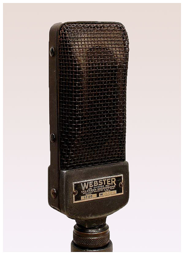
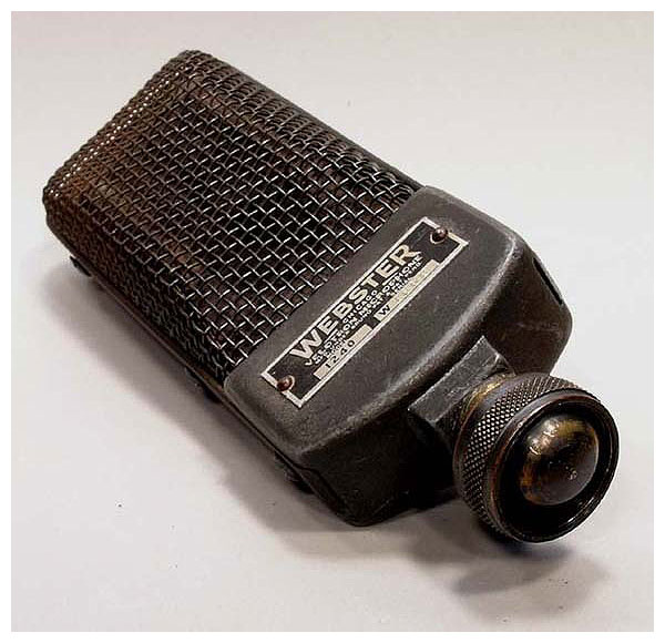
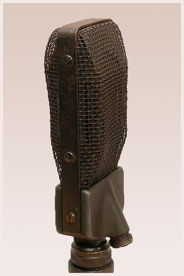
Photos above are courtesy of Dennis Schrank
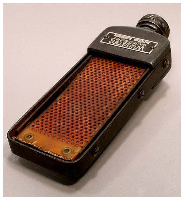
Dennis Schrank writes: “This old-timer was made by Bruno for Webster-Chicago. The Velotron was invented by William A. Bruno of the Bruno Laboratories way back in the mid nineteen thirties. It combines the principles of the ribbon microphone and the condenser microphone. It consists of a perforated plate covered by eight ribbons. This assembly is covered by another perforated plate. It then requires a polarizing voltage between 50 and 350 volts.
“This one is in good condition except the bottom of the swivel mount is missing, so it will take some improvising to mount it on a stand. Does it work? I have no idea, but these were not known for great reliability. Bruno was not in the microphone business for long, so these are rather scarce. It is a unique and unusual ribbon mic. See the following text for a 1936 magazine article explaining how it works, and even a schematic on how to power it up.”
Be sure to visit the Bruno page as well.
A Static Velocity Microphone
(Published in Electronics, September 1936)
A new and simple construction uses parallel ribbons and a perforated
plate to produce velocity characteristics in a capacity-type microphone.
The microphone department of the entertainment and communications industries has for some years been one of the most active in developing new instruments and new competitive methods of rating their output. The former activity is entirely commendable, the latter perhaps less so, but together they have conspired to make microphones a topic of interest to nearly every engineer connected with sound transmission. The latest development in the field, to the editors’ knowledge, is a new principle of construction applied to capacity microphones, which at once makes them much cheaper to manufacture and vastly easier to use in practice. The new microphone, called the Velotron by its inventor, William A. Bruno, of the Bruno Laboratories, New York, is of extremely simple construction, and it possesses several unusual technical features, particularly a high-frequency response which can be changed electrically from a remote location.
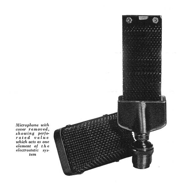
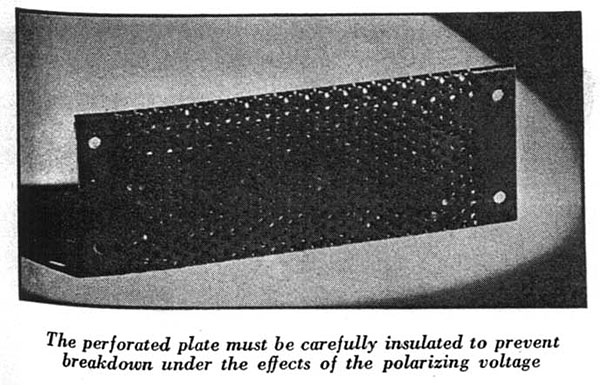
Fundamentally the new microphone combines the principles of the ribbon microphone and the condenser microphone. It consists of a flat insulated perforated plate, covered with a system of ribbons. The plate contains about 80 holes per square inch, each one-sixteenth of an inch in diameter. The insulation is applied in six coats, and the materials used are chosen to produce high insulation strength, especially at the sharp edges around each hole. Over the plate are laid eight ribbons (each 0.0002 inch thick) of duralumin, parallel to each other, with adjacent edges barely touching. The ribbons are fastened at their ends to the plate, and are free to move loosely toward or away from it. The ribbons act as one “plate” of the condenser microphone, the insulated plate as the other. The ribbon structure is protected by covering it with a second perforated plate similar in general appearance to the first but not so carefully insulated.
The principle of operation is as follows: A polarizing voltage of from 50 to 350 volts is applied between the electrodes; this voltage may be fed to the microphone over the same conductors which take the signal from it, and is applied through a ten-megohm resistor. Due to the fact that there is practically no current drawn by the microphone, filtering of the polarizing voltage is very easily accomplished, and the circuit shown in the figure below usually gives sufficient filtering even when the voltage is taken directly from the output of the rectifier unit, without passing through the usual filter sections. The leakage current through the microphone is extremely small, considerably less than one microampere. The effect of the difference of potential is to draw the ribbons against the perforated plate, with an attraction which depends directly on the value of the polarizing voltage.
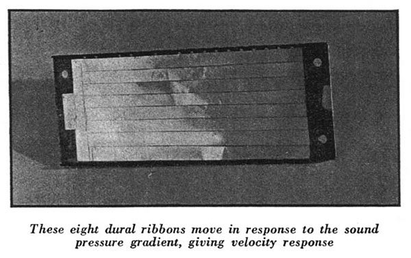
When the sound pressure gradient acts on the ribbons, they move slightly with respect to the perforated plate, thus changing the capacity of the system. This change in capacity produces a corresponding variation in the charge drawn from the polarizing circuit; the resulting current produces a voltage change across a high resistance (5 to 50 megohms) connected in series with the microphone, and this voltage change affects the grid of the amplifier. The use of a large surface area in the unit (four by one and a half inches) gives a large overall capacity, with resulting high signal level. Each perforation in the plate, together with the part of the ribbon immediately behind it acts as a contributing cell, the overall output being the sum of all the active cells acting in phase.
Several difficulties were encountered in the development. High output level was the first; operating stability the second. One of the most difficult problems was securing insulation between the capacity members which would withstand the effects of moisture. Even small variations in leakage resistance in a ten-megohm circuit can cause extremely troublesome noise levels. This problem has been solved by the use of proper insulating compounds; the noise level is far below signal output. The microphone operates on the velocity principle; that is, on the difference in sound-pressure existing on the two sides of the ribbons, although there is probably also a small output due to pressure-type response.
That the response is predominantly velocity-type is shown by two tests: the first is that the microphone has marked directional properties, the angle of response being somewhat broader than that of a magnetic-type velocity unit, but still very well marked. The second is the marked change in response which occurs when the side of the microphone away from the speaker is blocked in any way. The output of the unit at the present stage of development is –53 dB, or approximately the same as that of a diaphragm-operated crystal microphone. The signal output is considerably higher than that of magnetic-type velocity microphones.
The frequency response is, to the ear, approximately the same as that of a good magnetic velocity unit when moderate polarizing voltages and cable lengths of less than 100 feet are used. The microphone is, of course, a high impedance unit, working directly into the grid of the first amplifier tube. This fact makes the use of long lengths of cable connecting the microphone to the amplifier an obvious problem, the same problem in fact which made the use of head amplifiers imperative with conventional condenser microphones. That the problem still exists in the new microphone cannot be denied, but neither can the fact that the new unit can be operated with four hundred feet of shielded cable between the microphone and amplifier.
This remarkable performance has been obtained in several ways, first by making use of the high output signal level, and second by accentuating the high frequency which the capacity of the cable tends to attenuate. The high frequency “boosting” is accomplished by the use of a high value of polarizing voltage (about 350 volts), which attracts the ribbons to the perforated plate with great force, restricting wide-amplitude motions at low frequencies and allowing small-amplitude high-frequency motions to occur with comparative ease. By changing the polarizing voltage, the high-frequency response can be regulated in this manner by remote control.
The fact that the action of the microphone is electrostatic permits easy cable shielding and makes hum pick-up from electromagnetic fields very small. In fact the microphone and cable can be laid directly on the power transformer of the amplifier unit without audible hum pick-up. This treatment would completely paralyze magnetic units, as many of their users will testify, since magnetic shielding is difficult. Being a high-impedance unit, the microphone is not intended for use in the broadcast field, where low-impedance devices are usually required. But for public address and sound system use, where low-impedance units are impractical from a cost and operation standpoint, this new microphone should prove to be of considerable value.
Images above are courtesy of Dennis Schrank