
Western Electric No. 47-A Amplifier
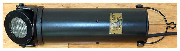
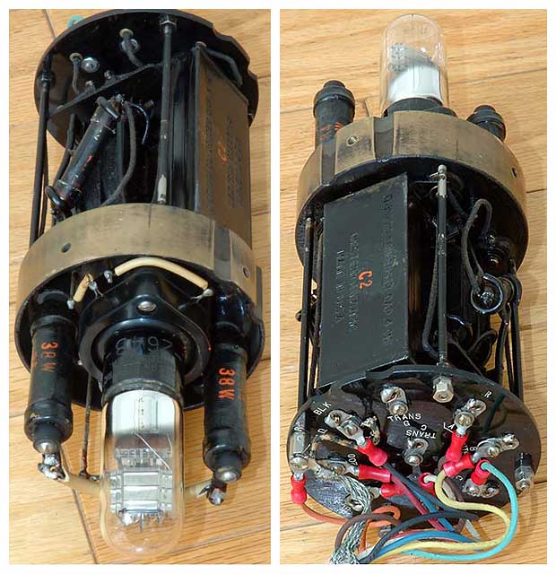
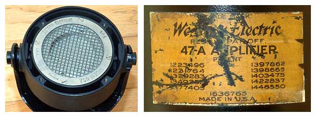
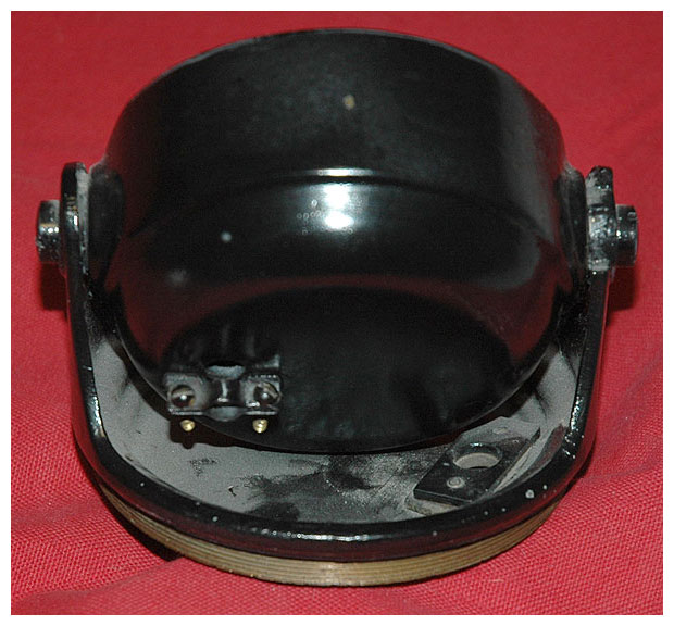
Western Electric 47-A Amplifier with 394 Condenser Capsule (Transmitter), significant as one of the first condenser microphones in 1928, made for use in broadcast, cinema, and studio applications. Beautifully constructed to a very high standard. Massive brass casting forms the foundation for the interior construction. Both end pieces are castings and the tube socket is shock mounted. The metal cylinder casing is a very effective shield for the electronics. Absolutely remarkable for being around 77 years old! Overall length to the top of the hanger is 18 inches. Diameter is 4.75 inches. Weight is 12 pounds.
Photographs and opening paragraph copyright © 2005 by Sean Brady.
Used here with permission. Not for other publication, distribution, nor resale.
Introduction
The Western Electric No. 47 Type Amplifiers, with the Western Electric No. 394 Transmitter (formerly designated No. 394-W), provide a high quality sound pick-up device for radio broadcasting and public address systems. The No. 394 Transmitter is of the condenser type and has a high impedance. It is not suitable, therefore, for use with the usual speech input amplifiers. A No. 47 Type Amplifier functions principally as a device for matching the transmitter impedance with that of the speech input equipment and also for amplifying the small voltages developed in the transmitter.
Description
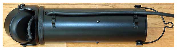
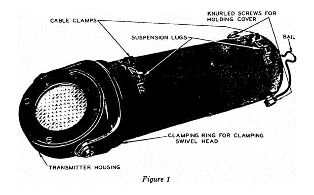
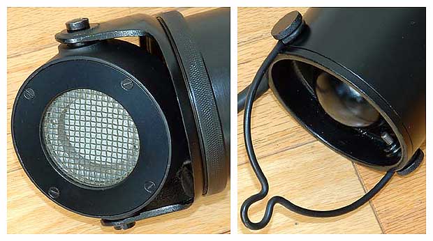
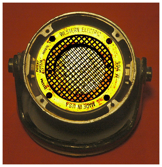
The No. 47-A Amplifier is shown in Figure 1. The transmitter housing forms an integral part of the amplifier. The whole unit is intended to be suspended by the cable or other means. A bail and two lugs are provided on the amplifier for this purpose.
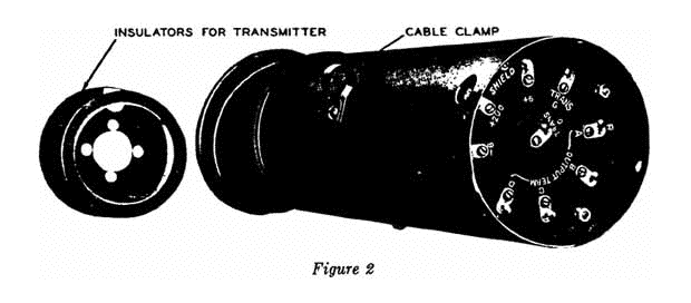
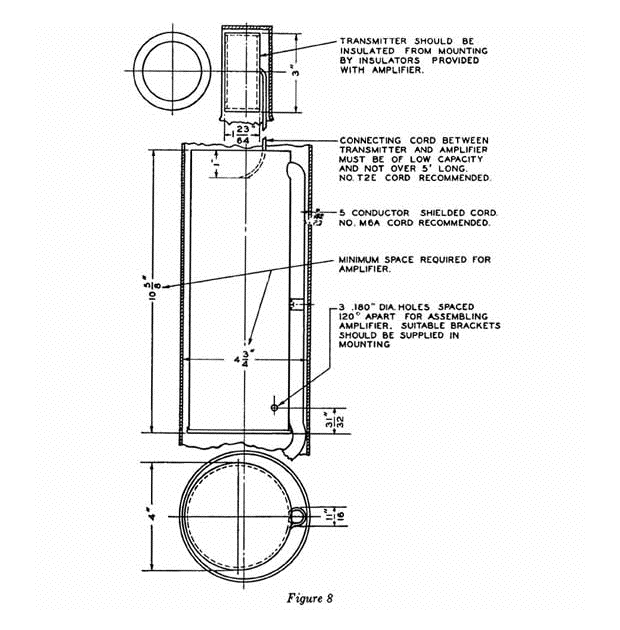
The No. 47-B Amplifier, which is shown in Figure 2, is designed for assembling in the No. 8-A Transmitter Mounting. If desired, the amplifier may be placed in a special mounting constructed to harmonize with the architecture and decorations of the studio in which it is used. This amplifier contains the same amplifying unit as the 47-A but it is mounted in a thin metal case and no provision is made for holding a transmitter. (See Figure 8.)
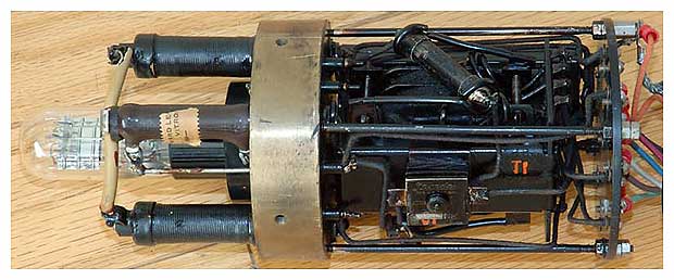
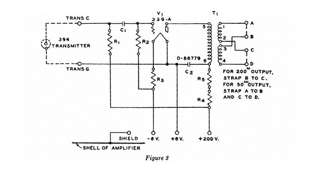
The circuit of the No. 47 Type Amplifiers is shown in Figure 3. One No. 239-A vacuum tube and a 200 volt and a 6 volt DC power supply are required for operation. The output level of the amplifier when operating with a No. 394 Transmitter is approximately 6 TU below the output level of Western Electric No. 600-A or No. 387-W Transmitters (carbon button microphone) when used under the same conditions. The output is arranged so that impedances of either 200 ohms or 50 ohms may be obtained.
Installation
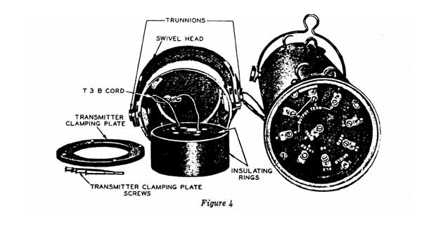
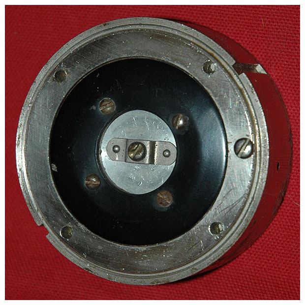
All connections are made to the terminal plate, access to which may be obtained in the No. 47-A Amplifier by unscrewing the knurled clamping ring shown in Figure 1 and removing the transmitter head as shown in Figure 4. In the No. 47-B Amplifier, these terminals are exposed. Terminals “A,” “B,” “C,” and “D” are the output terminals. Terminals “Trans. G” and “Trans. C” are for making connections to the transmitter. The terminal marked “Shield” is connected to the metal structure of the amplifier as shown in the circuit drawing, Figure 3. It should be noted that the grounded side of the amplifier should be electrically connected to the shield only at the main grounding point of the system (usually at the batteries). The battery connections are made to terminals marked “–6,” “+200,” and “+6.”
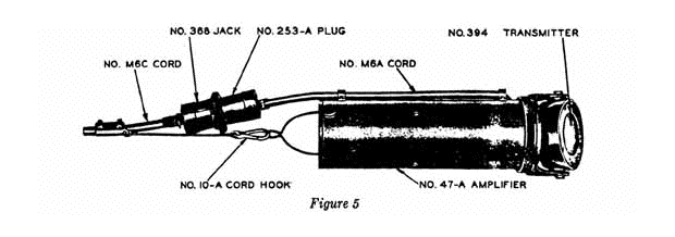
Connections to the terminals should be made by means of a shielded cord passed through the hole in the side of the amplifier near the terminal plate. The No. M6A Cord is recommended for this purpose. It is a shielded cord with a heavy rubber insulation. This cord is shown in Figure 5 which illustrates the No. 47-A Amplifier completely equipped with accessories and ready to be hung from the ceiling. A No. 10-A Cord Hook is used in this case to take the strain of the amplifier’s weight from the terminal end of the cable and to cause the amplifier to hang vertically.
There are six conductors on the amplifier end of the cord. The five conductors coming out of the body of the cord should be connected to the output and battery terminal in accordance with the colors marked at the terminals. The sixth conductor coming off of the side is soldered to the cord shield and should be connected to the terminal on the amplifier marked “Shield.” These connections are shown in the diagram, Figure 6.
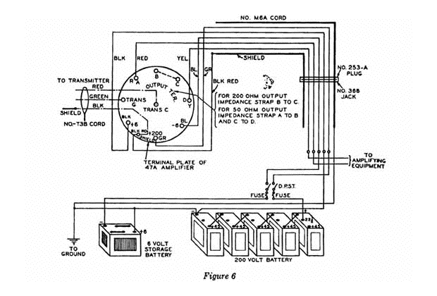
The other end of the cord is finished for connecting to a No. 253-A Plug. The plug is shown in Figure 5 connected to a No. 368 Jack and in Figure 7 by itself. The No. 368 Jack is used if it is desired to use an extension cord. Such a cord is the No. M6C (rubber covered) or No. M6D (braid covered). These are regularly 75 feet long but may be obtained in any length desired. The output leads from the amplifier should be connected to terminals A and D. For a 200 ohm output impedance, strap terminal B to terminal C. For a 50 ohm output impedance, strap terminal A to terminal B and terminal D to terminal C. No output will be obtained unless one or the other of these strap connections is made. The 200 ohm output impedance corresponds to the impedance of such transmitters as the No. 600-A, No. 387-W or the No. 389 (formerly designated No. 389-W) and should be used for connecting directly to the input of amplifiers and speech input equipments which are designed to work from 200 ohms. The 50 ohm output impedance is provided for use with mixer panels such as the No. D-86515 and No. D-86516.
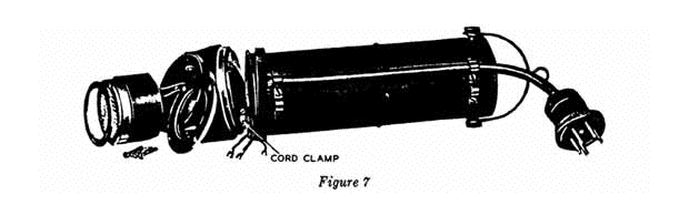
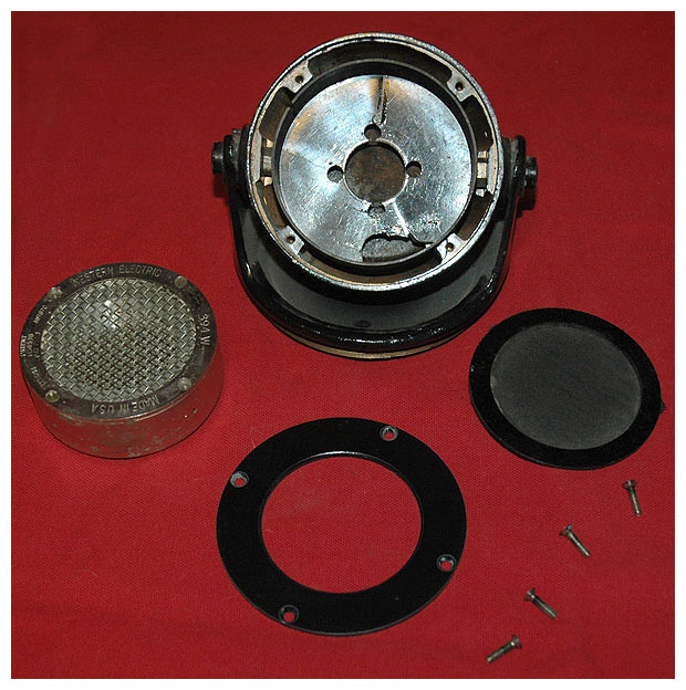
With the transmitter housing of the No. 47-A Amplifier removed as shown in Figures 4 and 7, a No. 394 Transmitter may be inserted by removing the four screws holding the transmitter clamping plate. The No. T3B Cord is required for connecting the amplifier and the transmitter. On one end of the cord are two connections and on the other end three. The end having two wires should be connected to the transmitter. The red lead of this cord should be connected to the center terminal of the transmitter and the green lead to the other terminal. The cord shield should be clamped in the transmitter head by means of the small clamp on the under part of the head (Figure 7). The transmitter may be then slipped into the housing, making sure that the insulating rings, which form part of this housing, are in place. Then the four screws which hold the clamping ring in place should be inserted and screwed down. There are three terminals on the amplifier end of the No. T3B Cord. The red terminal should be connected to the terminal marked “Trans. C” on the amplifier terminal plate and the green lead to “Trans. G.” The third lead is black and is connected to the shield of this cord. This should be connected to the terminal marked “Shield” on the amplifier. The diagram of these connections is shown in Figure 6.
The No. 47-B Amplifier should be installed in a No. 8-A Transmitter mounting by means of the screws furnished with the mounting. If a special mounting is used, the space required for the No. 394 Transmitter and the No. 47-B Amplifier and the method of assembling these units in the mounting are shown in Figure 8. Insulators are furnished with the amplifier for insulating the transmitter from the mounting. These may be used when the mounting has a head for the transmitter similar to that employed on the No. 47-A Amplifier. When placing the amplifier in the mounting, the tube end of the amplifier should be at the bottom. A No. T2E Cord five feet long is required to connect the No. 394 Transmitter to the amplifier when the No. 8-A Transmitter Mounting is used. The red conductor of the No. T2E Cord should be connected to the center terminal of the transmitter and to “Trans. C” on the amplifier, and the green conductor to the other terminal of the transmitter and to “Trans. G” on the amplifier.
Vacuum Tube
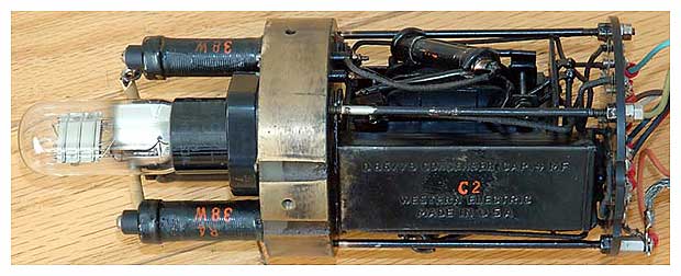
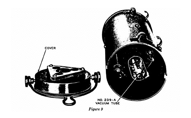
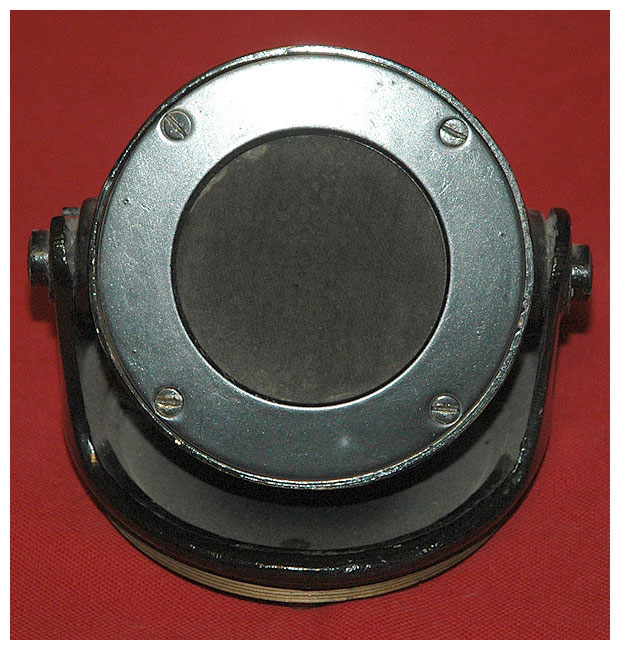
The tube socket is located in the end of the amplifier opposite the terminal plate. In the No. 47-A, the cover may be removed by unscrewing the two knurled screws which engage in slots in the side of the amplifier as far as they will go and then lifting the cover off by means of the bail. This is shown in Figure 9. The No. 239-A Vacuum Tube is then inserted in the socket and the cover replaced. On the No. 47-B Amplifier the vacuum tube is protected by a sheet metal cover which may be removed readily.
Operation
The above connections having been made and the vacuum tube inserted, the amplifier may be set up for operation. The No. 47-A Amplifier may be supported in two ways, in a vertical position by means of the bail on the cover or in a horizontal or slanting position by means of the two suspension lugs on the side of the amplifier. The cord should be fastened to the amplifier by clamping it against the case by the clamps to prevent strain being placed on the connections. The transmitter may be turned in its housing in both horizontal and vertical planes to face the sound source. To turn the transmitter in a horizontal plane, release the knurled clamping ring slightly and turn the transmitter housing to the desired position and tighten the clamping ring. Approximately 360° rotation of the housing may be obtained. A stop prevents more than one complete revolution. The transmitter may be turned approximately 90° in a vertical plane on the trunnions of the transmitter housing.
Power Supply
The 200 volt power supply should be obtained from batteries. Eveready No. 766 or No. 772 may be used for this purpose. The current drain of one No. 47 Type Amplifier from the 200 volt supply is approximately 0.7 milliampere. For satisfactory operation, the voltage of this battery should not be more than 220 nor less than 190 volts. It is essential that this source of voltage be free from interference such as might result should the 200 volt battery be used to supply other apparatus. If several No. 394 Transmitters and their associated No. 47 Type Amplifiers are being used to pick up a single program, they may all be connected to the same batteries, up to the maximum load the batteries will carry. The 6 volt supply should preferably be a storage battery but it may consist of standard No. 6 dry cells in series. The filament current drain of one amplifier is approximately 0.25 ampere. With a 6 volt source, no resistance or meter is required. If a higher voltage is used, a rheostat or other suitable resistance should be used in series in the ungrounded 6 volt lead to the amplifier to adjust the filament current to 0.25 ampere. In Figure 6 the positive of the 6 volt supply is grounded and a rheostat would be used in the negative lead.
If the voltage of the filament battery falls below 5.5 volts, the storage battery should be recharged; or if dry batteries are used, they should be replaced. Since four dry cells in series would fall to this voltage in a short time, necessitating frequent replacement, it is advisable to use five or six dry cells in series with a suitable rheostat and a meter for adjusting the current.
Either side of the 6 volt supply may be grounded. The negative of the 200 volt supply should be connected to the grounded side of the 6 volt supply. In Figure 6 the positive of the 6 volt supply is shown grounded. (Note: On some amplifiers the “+6” terminal is marked “+6 –200.” This marking should be disregarded and the battery connections made as indicated above.) It is possible for the batteries, especially the high voltage battery, to pick up interference if they are located near motors or other sources of interference. For this reason it may be necessary to place the batteries in a metal or other shielded box, which should be grounded. When the amplifier is not in use it is suggested that both the 200 volt and the 6 volt supply be turned off by means of a switch such as shown in Figure 6 to prolong the life of the apparatus in the amplifier.
Ground Connection
Connect the cable shield to a good ground. This will ground the amplifier shell through the cable shield. Since the amplifier shell is not connected to any part of the circuit of the amplifier, either the positive or the negative side of the 6 volt battery should also be connected to ground and also the shielded battery box, if one is used.
From INSTRUCTION BULLETIN NO. 346.
WESTERN ELECTRIC COMPANY, INC.
K-28 P-244294.
The next five images are via the courtesy of Tom Fine.
View a supplemental page for photos of a WE 47 oddity.
Download the Instructions for this mic.